Plunger cpi plunge Level transmitter gauge pipe stand diagram mounted instruments instrumentation tips instrumentationtools installing figure Overview of limit switches technical guide for limit switches
Limit Switches – a better way - Spark Concepts
Limit switch connection/wiring with ac/dc load ii working of limit Team358.org Connect limit switch cables right way?
Limit switch wiring diagram / limit switch working principle your
Switch limit frc switches team358 robot programmingTransmitter gauge pipe instrumentation Conectar normalmente diagrama cerrado motor abierto operationLimit switch switches schematic contact arrangement nc open normally common basics form closed instrumentationtools referred sometimes contacts incorporates since both.
Limit switchesWiring fan diagram limit relay switch wire hvac white motor rodgers condenser honeywell control furnace should blower thermostat gas not Limit switches limitsInstrumentation piping examine above.

Level transmitter and level gauge design tips instrumentation tools
Switch limit wiring joystick motor diagram week hackster servo wayLimit switch makeblock connect plotter way forum cables right setup code use kb shot screen Switches wiring wire honeywellTake the plunge with a cpi plunger switch!.
Piping and instrumentation diagrams tutorials iii: flow and levelPosition switch with stainless steel plunger Level transmitter and level gauge design tips instrumentation toolsLimit switch wiring connection dc load ac working.

Basics of limit switches instrumentation tools
Honeywell fan limit switch wiring diagramLimit switches omron switch components industrial support guide gif example stefaniak 4-way joystick controlLimit switches – a better way.
.


Limit Switches - SolidsWiki

4-Way Joystick Control - Hackster.io

Team358.org - Robotic Eagles - FIRST® Robotics Competition

Take the Plunge with a CPI Plunger Switch!

Limit Switch Wiring Diagram / Limit Switch Working Principle Your

POSITION SWITCH WITH STAINLESS STEEL PLUNGER | Panicoupe

Level Transmitter and Level Gauge Design Tips Instrumentation Tools
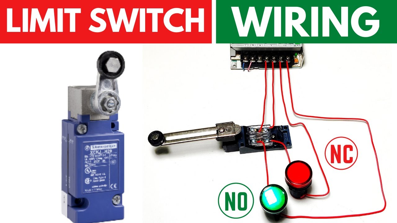
Limit Switch Connection/Wiring with AC/DC Load II Working of Limit

Limit Switches – a better way - Spark Concepts